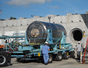
Areva NUHOMS Calvert Cliffs transfer cask. Thin-wall canister is inside transfer cask until it is inserted into concrete overpack hole. Concrete has air vents to cool thin-wall canister and fuel.
The Calvert Cliffs thin-wall stainless steel nuclear fuel waste dry storage canisters are vulnerable to cracking from the marine environment and other causes.
Calvert Cliffs has no plan in place to prevent or stop major radioactive releases into the environment. These canisters cannot be inspected for cracks, repaired or maintained. Monitoring radiation levels is only required once every three months.
According to the Nuclear Regulatory Commission (NRC), once a crack starts, it can grow through the canister wall in only 16 years. Canisters began loading in 1993.
In spite of knowing these problems, the NRC extended their 20 year dry storage site license for another 40 years. This Independent Spent Fuel Storage Installation (ISFSI) license renewal was approved October 23, 2014 and expires 11/30/2052.
The NRC requires an aging management plan, but is ignoring minimum requirements needed to monitor and maintain the dry storage system to prevent major radioactive leaks. Better systems are available that meet critical aging management safety requirements, but because the NRC refuses to enforce minimum safety requirements, nuclear facilities, such as Calvert Cliffs, continue to procure inferior nuclear fuel waste storage containers. Learn more…

Calvert Cliffs, Lusby, Maryland 20657
The ISFSI site license renewal allows them to continue using inferior thin-wall storage systems with vague statements like the one below from the NRC License Renewal Certificate ML14274A030. They do not mention that adequate inspection technology for thin-wall canisters (filled with lethal high-level nuclear fuel waste) does not exist. They do not require that technology be available that can thoroughly inspect for cracks and repair and maintain these canisters. They do not require the interior of the canisters to be inspected. They only need to inspect external surfaces using “proven technology reasonably available“, which is vague and inadequate.
The licensee shall perform inspections of DSC [dry storage canister] external surfaces using proven technology reasonably available at the time the inspection is conducted which is capable of meeting the physical access and environmental constraints of the HSM (concrete overpack) interior.
The NRC does not require inspection of the contents of the canister, even though they know both the fuel assemblies and fuel assembly baskets can degrade after dry storage, based on operating experience and experiments.
Calvert Cliffs ISFSI License Renewal Documents
The NRC created a webpage for the Calvert Cliffs ISFSI license renewal, but has refused to put any documents on that webpage. Below are links to the documents that should be on that webpage.
ML14274A022 Webpage – Issuance Of Renewed Materials License No. SNM-2505 for the Calvert Cliffs Site Independent Spent Fuel Storage Installation, Docket 72-8, TAC No. L24475, ML14274A022, 10/23/2014 https://www.nrc.gov/docs/ML1427/ML14274A022.html
- ML14274A020 – NRC Letter to Calvert Cliffs, Exelon, Issuance of Renewed Materials License No. SNM-2505 for the Calvert Cliffs Site Specific ISFSI, 10/23/2014, https://www.nrc.gov/docs/ML1427/ML14274A020.pdf
- ML14274A027 – NRC Federal Register Notice of Issuance, no significant impact, Docket No. 72-8, Calvert Cliffs ISFSI Renewed Materials License No. SNM-2505, 10/23/2014
https://www.nrc.gov/docs/ML1427/ML14274A027.pdf - ML14274A030 – NRC ISFSI License Renewal Certificate (CoC), Calvert Cliffs, 10/23/2014 [expires 11/30/2052] https://www.nrc.gov/docs/ML1427/ML14274A030.pdf
- ML14274A033 – Appendix A Technical Specifications, Calvert Cliffs Independent Spent Fuel Storage Installation, Materials License No. SNM-2505, 10/23/2014
https://www.nrc.gov/docs/ML1427/ML14274A033.pdf - ML14274A038 – Safety Evaluation Report for License Renewal Calvert Cliffs Nuclear Power Plant Independent Spent Fuel Storage Installation, Docket No. 72-08, License No. SNM-2505, 10/23/2014 https://www.nrc.gov/docs/ML1427/ML14274A038.pdf
- ML14274A041 – Revised Aging Management Programs, SER Appendix A, Calvert Cliffs ISFSI renewal, Materials License No. SNM-2505, 9/18/2014 https://www.nrc.gov/docs/ML1427/ML14274A041.pdf
- ML14274A043 – Federal Register Notice of Issuance, Calvert Cliffs ISFSI renewal, Materials License No. SNM-2505, Docket No. 72-8, 10/23/2014 https://www.nrc.gov/docs/ML1427/ML14274A043.pdf
Calvert Cliffs ISFSI NRC Requests for Additional Information (RAIs)
- ML102650247 – Application for ISFSI Renewal of Site Specific License, 9/17/2010 http://www.nrc.gov/docs/ML1026/ML102650247.pdf
- ML110620134 – Response to First Request for Supplemental Information, 2/10/2011 (zipfile)
https://adamswebsearch2.nrc.gov/webSearch2/main.jsp?AccessionNumber=ML110620134- ML110620120 – License Renewal Application Response to Request for Supplemental Information, 2/10/2011 4.32 Mb https://adamswebsearch2.nrc.gov/webSearch2/main.jsp?AccessionNumber=ML110620120
- ML110620151 – USAR Change 50.59 Log No. 94-0-101-001, Applicable to 10 CFR 50.59 and 10 CFR 72.48 Safety Evaluations, 2/10/2011 38.21 Mb https://adamswebsearch2.nrc.gov/webSearch2/main.jsp?AccessionNumber=ML110620151
- ML110620159 – EN-1-102, Revision 4, “ISFS – HSM Rail Alignment Tolerance Requirements”, 11/07/1997 34.51 Mb https://adamswebsearch2.nrc.gov/webSearch2/main.jsp?AccessionNumber=ML110620159
- ML110620161 – EN-1-102, Revision 4, “ISFSI – Transfer Cask Lead Silver Content Non Conformance”, 11/7/1977, 36.01 Mb https://adamswebsearch2.nrc.gov/webSearch2/main.jsp?AccessionNumber=ML110620161
- ML110730720 – Response to Second Request for Supplemental Information, 3/9/2011 (zipfile)
https://adamswebsearch2.nrc.gov/webSearch2/main.jsp?AccessionNumber=ML110730720- ML110730731 – Response to Second Request for Supplemental Information, 3/9/2011
https://adamswebsearch2.nrc.gov/webSearch2/main.jsp?AccessionNumber=ML110730731 - ML110730740 – Calculation No. 1095-6, Rev. 1, NUHOMS-32P – Transfer Thermal Analysis, 103F Ambient, 5/21/2004
https://adamswebsearch2.nrc.gov/webSearch2/main.jsp?AccessionNumber=ML110730740 - ML110730742 – Calculation no. 1095-16, Rev. 0, Transfer Thermal Analysis, -3F Ambient, 7/1/2003
https://adamswebsearch2.nrc.gov/webSearch2/main.jsp?AccessionNumber=ML110730742 - ML110730752 – Calculation No. 1095-35, Rev. 2, NUHOMS-32P – Transfer Cask Structural Analysis, 4/14/2004 https://adamswebsearch2.nrc.gov/webSearch2/main.jsp?AccessionNumber=ML110730752
- ML110730760 – Calculation No. 1095-49, Rev. 0, NUHOMS-32P – Radiation Dose Rates for Loading and Transfer, 8/25/2003 https://adamswebsearch2.nrc.gov/webSearch2/main.jsp?AccessionNumber=ML110730760
- ML110730769 – NUH-002, REV. 2A, Topical Report for the NUTECH Horizontal Modular Storage System for Irradiated Nuclear Fuel NUHOMS-24P, VOLUME I, 4/30/1991
https://adamswebsearch2.nrc.gov/webSearch2/main.jsp?AccessionNumber=ML110730769
- ML110730731 – Response to Second Request for Supplemental Information, 3/9/2011
- ML11180A270 – Response to First Request for Additional Information, 6/28/2011 https://adamswebsearch2.nrc.gov/webSearch2/main.jsp?AccessionNumber=ML11180A270
NRC RAI 3-5: Provide rationale that the stainless steel subcomponents of the HSM exposed to a yard or yard-salt environment are not subject to the aging effects of stress corrosion cracking and loss of material due to corrosion.
In Section 3.4.5 the applicant did not identify any aging effects that require management for a number of stainless steel subcomponents exposed to a yard environment. NUREG-1801, Rev. 2, indicates that the aging effects of stress corrosion cracking and loss of material due to pitting and crevice corrosion could occur for stainless steel components exposed to an outdoor air environment. The corrosion testing documented in NUREG/CR-7030 shows that stainless steel materials are susceptible to stress corrosion cracking in coastal marine environments. This is required to evaluate compliance with 10 CFR 72.120. - ML113640129 – Response to Second Request for Additional Information, 12/15/2011 (zipfile)
https://adamswebsearch2.nrc.gov/webSearch2/main.jsp?AccessionNumber=ML113640129- ML11364A024 – Response to Second Request for Additional Information, 12/15/2011
https://adamswebsearch2.nrc.gov/webSearch2/main.jsp?AccessionNumber=ML11364A024
CCNPP Response 0-1: Routine surveys are performed yearly at the ISFSI storage facility in accordance with Calvert Cliffs procedure for routine radiological surveys. The primary purpose of these surveys is to establish radiological protection requirements for plant personnel, including ensuring hazards in the area are identified with the proper radiological postings. These surveys also ensure that dose rates at the Calvert Cliffs ISFSI remain below the regulatory requirements of 10 CFR 72.104.
The current revision of this procedure only requires one specific set of measurements for ISFSI routine surveys: dose rates at the ISFSI Controlled Area fence. This procedure specifies that dose rates at the fence cannot exceed 500 micro-rem/hr (0.5 mremlhr). No additional survey points for the ISFSI storage area or HSMs are required by this procedure.
Even though there are no specific HSMs survey points required by this procedure, surveys of the ISFSI facility have been relatively consistent since these surveys were first performed. These surveys consist of contact and 12 inch dose rates taken on the front of the HSMs, typically at the air intake screen where the dose rate is highest (due to there being less shielding at this location than the rest of the front of the HSM). [NOTE: With through-wall cracks, dose rate would be highest at the outlet air vents. Why are they not measuring this?] - ML11364A025 – Enclosure 2, Calculation CA07718, 2011 Update of ISFSI USAR DSC Leakage Dose Analysis, 12/15/2011 https://adamswebsearch2.nrc.gov/webSearch2/main.jsp?AccessionNumber=ML11364A025
- ML11364A024 – Response to Second Request for Additional Information, 12/15/2011
- ML12212A216 – Response to Third Request for Supplemental Information, 7/27/2012
https://adamswebsearch2.nrc.gov/webSearch2/main.jsp?AccessionNumber=ML12212A216
On the upper shell of both DSC-6 and DSC- 11, a thick coat of dust and small clumps of unknown material were observed, as shown on Figure 2, except near the outlet vent where there is evidence of water coming in contact with the DSC. As these water marks were observed only near the rear outlet vent, they are likely created by wind driven rain water entering the module via the rear outlet vent. In the case of DSC- 11, the heat shield fastener on the ceiling directly above the water mark was observed to have a white stain around it. No signs of rust were seen in areas where water marks were observed. In the case of DSC- 11, a sample of the dust deposited on the top surface was collected from a known area as part of the EPRI scope of the inspection. The analysis. of the composition and salt concentrations measured will be presented in their report later this year. [See document for photos of water, scratches and dust]. - ML131700610 – Partial Response to Third Request for Additional Information, 6/14/2013 (zipfile)
https://adamswebsearch2.nrc.gov/webSearch2/main.jsp?AccessionNumber=ML131700610- ML13170A574 – Response to Request for Additional Information 6/14/2013 8.91Mb
https://adamswebsearch2.nrc.gov/webSearch2/main.jsp?AccessionNumber=ML13170A574 - ML13170A575 – Calculation No. 10955-0401, Rev. 1 “outer Surface Weld Temperature of the NUHOMS 24P and 32P DSCs Stored at CCNPP ISFSI Site,” Enclosure 7, Non-Propriety, 6/6/2013 3.84 Mb https://adamswebsearch2.nrc.gov/webSearch2/main.jsp?AccessionNumber=ML13170A575
- ML13170A571 – Engineering Evaluation No. 10955-EE-00, Rev. 1, CCNPP ISFSI: Canister Cask Stress Corrosion Cracking Review for License Renewal, 6/11/2013 5.66 Mb
https://adamswebsearch2.nrc.gov/webSearch2/main.jsp?AccessionNumber=ML13170A571 - ML13170A572 – Document No. 86-9205756-000, “summary of SCC Assessment of SS Welds in 24P and 32P NUHOMS Dry Storage Casks.” Enclosure 9, Non-Proprietary, 6/7/2013 3.19 Mb https://adamswebsearch2.nrc.gov/webSearch2/main.jsp?AccessionNumber=ML13170A572 [Useless. Data variables made proprietary.]
- ML13170A573 – Calculation No. 10955-0402, Rev. 1, “To Determine Time Limit for Exposure of the Fuel Cladding to oxidizing Atmosphere for the 24P and 32P DSCs Stored at the CCNPP ISFSI Site,”, Enclosure 10, Non-Proprietary, 6/6/2013 3.19Mb
https://adamswebsearch2.nrc.gov/webSearch2/main.jsp?AccessionNumber=ML13170A573
The welds on the DSC shells are potentially affected by the stress corrosion cracking (SCC) after long-term storage. Hypothetically, the DSC shell may be compromised due to SCC. Under this hypothetical condition the helium may get released from the DSC cavity and be replaced by air. This calculation determines the maximum exposure time that fuel cladding within the NUHOMS® 24P and 32P DSCs during long-term storage at the CCNPP ISFSI remain undamaged when exposed to an oxidizing atmosphere after the DSC shell is compromised due to stress corrosion cracking (SCC). Numerous references:
7. Oxidation of Spent Fuel at Between 250 and 360°C”, EPRI NP-4524, April 1986
10. SANDIA Report, SAND90-2406, “A Method for Determining the Spent Fuel Contribution to Transport Cask Containment Requirements,” 1992.
4.1 Environmental Conditions and Heat Loads.
It is expected that the maximum heat loads for 24P DSC and 32P DSC are reduced to approximately between 4 kW and 6 kW after long-term storage at the CCNPP ISFSI site. Therefore, heat loads of 4 kW to 6 kW are assumed for the 24P and 32P DSCs after long-term storage at the CCNPP ISFSI site when the DSC shell may hypothetically be compromised due to SCC. The results of this evaluation are valid [only] for any 24P DSC and 32P DSC with maximum heat loads below 6 kW at CCNPP ISFIS site regardless of the storage time since the maximum heat loads as the used as inputs.
The DSC shell temperature profile for 6 kW heat load is retrieved directly from result files of the CFD model described in [6] and applied as a boundary condition for the 24P and 32P DSC models. [If criticality, kW will be higher. Also, won’t fuel become damaged with criticality? Also, why assumption for low kW at time of leak?]
6.4 Fuel Oxidation Time Limit
The fuel rods in the CCNPP DSCs may hypothetically be exposed to air once DSC through wall crack propagation occurs from SCC. If the temperature of the fuel rods is high enough and if the time is sufficient for UO2 to oxidize to U3O8, then a stress is placed on the fuel rod cladding because of the reduction in fuel density from 10.4 g/cm 3 to 8.4 g/cm 3 [7]. Such stress can cause the cladding to be compromised and split open. [Doesn’t address uranium hydrides or other hydriges and risk for hydrogen explosion.]
7.0 RESULTS Page 20
Table 7-1 CCNPP DSC Maximum Temperatures for 4 kW and 6 kW Heat Loads
6 kW, cooled 28 years, Max Clad Temp 447F, Time to Split 2.9 years. [Doesn’t address high burnup fuel.]
- ML13170A574 – Response to Request for Additional Information 6/14/2013 8.91Mb
- ML131190290 – Supplemental Response to Third Request for Additional Information, 4/24/2014 (zipfile)
https://adamswebsearch2.nrc.gov/webSearch2/main.jsp?AccessionNumber=ML131190290- ML13119A242 – Response to Request for Additional Information Regarding the License Renewal Application, Part 1 of 3, 4/24/2013 567.99 Kb https://adamswebsearch2.nrc.gov/webSearch2/main.jsp?AccessionNumber=ML13119A242
- ML13119A243 – Calvert Cliffs, Independent Spent Fuel Storage Installation, Response to Request for Additional Information Regarding the License Renewal Application, Part 2 of 3. 4/24/2013 https://adamswebsearch2.nrc.gov/webSearch2/main.jsp?AccessionNumber=ML13119A243
[Attachment (1) includes dry storage inventory.]
Due to the fact that the NUHOMS® DSCs in use at the Calvert Cliffs Independent Spent Fuel Storage Installation (ISFSI) are uninstrumented and utilize a welded closure method, there is no practical method to sample the interior fill gas or inspect the fuel being stored.
On April 16, 2013 DOE awarded this contract to an Electric Power Research Institute (EPRI) team. Calvert Cliffs directly supports EPRI through our financial support of that organization and is an active participant on the steering committee for the team which prepared the bid. This will ensure Calvert Cliffs has input on the direction of the project and will be able to apply information learned from this project to the aging management program for HBF stored at Calvert Cliffs. [We’re paying for this DOE Demonstration Project with ratepayer and taxpayer money. The NWTRB said it won’t prove anything and is a waste of money].
Interim Staff Guidance (ISG)- 11 Revision 3 (Reference 1-4) indicates that “based on staffs evaluation, it is expected that fuel assemblies with burnups less than 45 GWd/MTU are not likely to have a significant amount of hydride reorientation due to limited hydride content.
Further, most of the low burnup fuel has hoop stresses below 90 MPa. Even if hydride reorientation occurred during storage, the network of reoriented hydrides is not expected to be extensive enough in low burnup fuel to cause fuel rod failures.” Based on this, the fuel stored in 24P DSCs is considered to not be at significant risk from the aging management concerns associated with extended storage of HBF. The 24 loaded 32P DSCs do however contain significant amounts of fuel that fall into the lower range of the HBF category. [Mid range burnup operating date shows otherwise, but NRC refuses to address this.]
[Partial inventory of 32PT casks in this report.] Scotch Brite pads to scrape dust particles from DSC. [Report includes photos.] - ML13119A244 – Calvert Cliffs, Independent Spent Fuel Storage Installation, Response to Request for Additional Information Regarding the License Renewal Application, Part 3 of 3, 4/24/2013 https://adamswebsearch2.nrc.gov/webSearch2/main.jsp?AccessionNumber=ML13119A244
The purpose of this analysis was to determine the compositions of particulate matter collected on various substrates. Three samples were analyzed along with clean duplicates as controls (six samples total). The materials analyzed included polyester filters identified in this report as “Filter Used” and “Filter Control”; Scotch-Brite pads (Used and Control); and thin polypropylene or polyethylene filters associated with SaltSmart analyzers (SaltSmart Used and SaltSmart Control).
- ML14175B035 – Calvert Cliffs Independent Spent Fuel Storage Installation – Fourth Request for Additional Information for Renewal Application to Special Nuclear Materials License No. 2505, 6/23/2014 https://www.nrc.gov/docs/ML1417/ML14175B035.pdf
- L14267A065 – Calvert Cliffs Independent Spent Fuel Storage Installation – Response to Fourth Request for Additional Information for Renewal Application to Special Nuclear Materials License No. 2505, 9/18/2014
https://www.nrc.gov/docs/ML1426/ML14267A065.pdf
CISCC propagation rates are known to be strongly temperature dependent. Testing by Hayashibara et al. (2008) reported activation energy for crack growth in type 304 stainless steel of 5.6 to 9.4 kcal/mol (23 to 39 kJ/mol) based on testing conducted at temperatures of 50 to 80 degrees C. Taking the median crack propagation rate reported by Kosaki (2008) of 9.6 x 10(12) m/s and assuming that rate was measured under exposure temperatures typical of Miyakojima Island (average temperature of 23 degrees C) and the median activation energy of 31 kJ/mol reported by Hayashibara et al. (2008), the SCC propagation rate increases by 2x at 40 degrees C, 3x at 51 degrees C; and 4x at 60 degrees C. Because the temperature of the canisters will initially be at temperatures well above ambient, the effect of temperature on crack propagation rates must be included in the assessment of the time necessary for through wall cracking. This information is required to evaluate compliance with 10 CFR 72.24 (d) and 10 CFR 72.122(b)(1) and (h)(5).
Partial Inspection of Selected Calvert Cliffs Canisters
- Thermal Modeling of NUHOMS HSM-15 and HSM-1 Storage Modules at Calvert Cliffs Nuclear Power Station ISFSI, PNNL-21788, Pacific Northwest National Laboratory for Dept. of Energy (DOE), Sarah R. Suffield, James A. Fort, Harold E. Adkins, Judith M. Cuta, Brian A. Collins, Edward R. Siciliano, October 1, 2012.
https://digital.library.unt.edu/ark:/67531/metadc844032/m2/1/high_res_d/1055414.pdf
On June 27th and 28th, 2012, visual inspections, surface sampling, and temperature measurements were performed on HSM-1 and HSM-15 at the Calvert Cliffs Nuclear Power Station ISFSI. Due to physical constraints on the accessible regions of the DSC and considerations of worker safety, reliable temperature measurements were obtained only on the exposed face of the canister base. Temperature measurements were taken by touching a hand-held thermocouple probe to the surface of the canister and recording the reading on a data sheet. Figure S.7 illustrates the specific locations sampled in this manner on the accessible exposed face of the canister (which is the canister base, due to the prescribed loading configuration). Measured temperatures (Table S.3) on HSM-1 ranges from 104 degrees F (40 degrees C) to 115 degrees F (46 degrees C).
- ML17297A414 – Calvert Cliffs – ISFSI AMP Update & Lessons Learned, Jack DeSando, Manager, ISFSI Implementation & Support, Exelon Generation Company, LLC, October 31, 2017 (ML17297A414) https://www.nrc.gov/docs/ML1729/ML17297A414.pdf
In this slide presentation, Exelon admits they only used a camera to inspect the outside of the thin-wall canisters. That is not sufficient to find microscopic cracks. They are only using this, because no other option is available. See below document by Parrott that identifies the pros and cons of each option. - Chloride stress corrosion cracking in austenitic stainless steel, Assessing susceptibility and structural integrity, UK, prepared by the Health and Safety Laboratory for the Health and Safety Executive, 2011 R Parrott, et. al., SK17 9JN. The following applies to inspections in vessels and pipes, but indicates the limitations of various inspection options, even in containers without spent nuclear fuel.
…Leak detection is not a reliable indicator of CLSCC [chloride stress corrosion cracking] because cracks are highly branched and may be filled with corrosion products. Nevertheless, it is recommended that where pipework or vessels develop leaks in service, they should always be investigated for possible CLSCC by NDE non-destructive examinations] or by in-situ metallography.
CLSCC can generate very large cracks in structures where, as in the case of reactors, the residual stress from welding dominates and operational stresses are low by comparison. If undetected by NDE, the large cracks might introduce failure modes with consequences that were not anticipated by the original design, e.g. complete separation of attachments, toppling of tall columns under wind loading or collapse of long pipe runs due to self-weight.
The simplest and most effective NDE technique for detecting CLSCC is dye penetrant testing. Eddy Current Testing (ECT) is effective with purpose-designed probes that have been calibrated on known defects. ECT was found to be ineffective on the samples from the reactor due to limited penetration of the current and sensitivity to surface imperfections that could not be distinguished from cracking.
Crack sizing by eddy current testing may be limited and is not possible by penetrant testing.
Ultrasonic flaw detection can be applied as a manual or an automated NDE technique for detecting CLSCC. For structures with complex design features and welds as on the reactors, the trials indicated that ultrasonic testing would require a range of probes, several complimentary scans and be very time consuming. Ultrasonic flaw detection did not cover all design details and possible crack position orientations found on the reactor, and crack sizing was difficult.


